Custom Efoil Surfboard Supplier
Custom Efoil Surfboard Supplier
Selecting a supplier for custom efoil surfboards requires evaluating engineering capabilities, material compatibility, and production precision. This page details the technical considerations involved in specifying and procuring custom efoil systems, focusing on factors that influence performance, safety, and lifecycle value.
Core Technical Components of Custom Efoil Systems
A functional efoil surfboard integrates four primary subsystems: the hydrofoil assembly, electric propulsion unit, battery enclosure, and control interface. Each subsystem must be engineered to withstand marine corrosion, dynamic loading, and thermal cycling while maintaining hydrodynamic efficiency and weight targets.
The hydrofoil assembly—comprising mast, fuselage, and wings—generates lift through precise foil geometry and angle of attack. Critical parameters include aspect ratio, wing area, and thickness-to-chord ratio, which directly affect stall speed, lift-to-drag ratio, and maneuverability. Fuselage length influences pitch stability, while mast height determines clearance above water and affects drag during takeoff.
The electric propulsion unit consists of a waterproof motor, propeller, and electronic speed controller (ESC). Motor selection depends on required thrust (typically 5–15 kW for recreational use), Kv rating, and cooling method (liquid-cooled vs. passive). Propeller design must balance efficiency, cavitation resistance, and clearance from the fuselage. ESC firmware governs throttle response, regenerative braking, and thermal protection thresholds.
Battery enclosures must protect lithium-ion cells from water ingress, impact, and thermal runaway while optimizing weight distribution. Key factors include cell chemistry (NMC, LFP, or LCO), pack voltage (commonly 48V–72V), energy density (Wh/kg), and cooling strategy. Enclosure materials must resist saltwater corrosion and maintain structural integrity under repeated flexing cycles.
The control interface—typically a handheld wireless remote—transmits throttle commands via encrypted RF or Bluetooth. Latency, signal reliability in wet conditions, and failsafe behavior (e.g., motor cutoff on signal loss) are critical safety factors. Ergonomics, grip texture, and button tactility affect usability during operation.
Material Selection and Engineering Trade-offs
Material choices significantly influence weight, stiffness, corrosion resistance, and manufacturing complexity. Carbon fiber reinforced polymer (CFRP) is commonly used for hydrofoil masts and fuselages due to its high specific stiffness and fatigue resistance. However, layup quality, resin selection, and cure cycle directly impact interlaminar strength and void content.
Wing components often use CNC-machined aluminum alloys (e.g., 6061-T6 or 7075) or molded CFRP. Aluminum offers better impact resistance and easier repair but higher density. CFRP wings provide superior stiffness-to-weight ratios but require careful edge sealing to prevent water absorption and delamination. Surface finish affects boundary layer transition and drag.
Battery enclosures frequently employ marine-grade aluminum (5052 or 5083) or reinforced polymers (e.g., ABS-PC blends) with silicone gaskets and potting compounds. Sealing effectiveness is validated via IP68 testing (immersion beyond 1m for 30 minutes). Thermal management may include phase-change materials or conductive pads to transfer heat from cells to the enclosure wall.
Fasteners and hardware must be corrosion-resistant—typically titanium (Grade 5) or marine-grade stainless steel (A4-316). Galvanic isolation between dissimilar materials (e.g., carbon fiber and aluminum) is essential to prevent electrolytic corrosion. Insulating washers or coatings are commonly applied at interfaces.
Customization Parameters and Design Logic
Customization begins with defining operational requirements: target user weight, intended use case (cruising, wave riding, instruction), typical water conditions (salt/fresh, chop, waves), and regulatory constraints (speed limits, noise). These inputs drive hydrofoil sizing, power system selection, and stability tuning.
For heavier riders (>100 kg), increased wing area and/or higher aspect ratio foils are typically required to achieve sufficient lift at low speeds. Conversely, lighter riders (<70 kg) benefit from smaller, higher-aspect wings for improved responsiveness and reduced drag. Fuselage length is adjusted to balance pitch stability with turning agility—longer fuselages suit beginners; shorter ones favor advanced maneuvers.
Battery capacity is calculated based on desired ride time, average power draw, and depth-of-discharge limits. A 60-minute cruise at 8 kW average draw requires approximately 160 Wh usable capacity (factoring in 80% DoD for lithium-ion). Real-world range varies with speed, rider weight, and water conditions—higher speeds exponentially increase power demand due to drag scaling with velocity cubed.
Motor Kv is selected to match propeller characteristics and battery voltage. Higher Kv motors spin faster at lower torque, suitable for small-diameter, high-RPM propellers. Lower Kv motors deliver higher torque at lower RPM, ideal for larger, slower-spinning propellers that operate more efficiently. Propeller diameter and pitch are chosen to avoid cavitation while achieving target thrust at operating RPM.
Control system tuning includes throttle response curves, regenerative braking strength, and low-voltage cutoff settings. Soft start profiles reduce inrush current and improve stability during takeoff. Regenerative braking can extend range by recovering energy during deceleration but must be carefully modulated to avoid sudden nose-down pitching.
Quality Control and Validation Process
Manufacturing quality is verified through dimensional inspection, material testing, and functional validation. Hydrofoil geometries are checked using CMM or laser scanning to ensure foil symmetry, twist distribution, and surface smoothness within tolerances (typically ±0.5 mm for critical dimensions). Layup integrity is assessed via ultrasonic testing or tap testing to detect delaminations or voids.
Battery enclosures undergo hydrostatic pressure testing (e.g., 2 bar for 10 minutes) and thermal cycling (-20°C to +60°C) to validate sealing and mechanical robustness. Insulation resistance is measured between terminals and enclosure to ensure isolation (>100 MΩ). Cell balancing and voltage monitoring are verified during charge/discharge cycles.
Propulsion systems are tested on dynamometers to measure thrust, torque, efficiency, and temperature rise across the operating range. ESC firmware is validated for fault detection (overcurrent, overtemperature, undervoltage) and failsafe behavior. Wireless controllers are tested for signal strength, latency (<50 ms), and interference resistance in marine environments.
Final assembly includes alignment checks (motor shaft to propeller, mast to board), torque verification of fasteners, and waterproofing validation. Sea trials assess handling, stability, thrust response, and battery performance under real-world conditions. Data logging captures speed, depth, motor temperature, and battery voltage for post-analysis.
Typical Specifications and Customization Options
| Parameter | Typical Range | Customizable? |
|---|---|---|
| Hydrofoil Mast Height | 600–900 mm | Yes (in 50 mm increments) |
| Front Wing Area | 1200–2000 cm² | Yes (custom profiles available) |
| Fuselage Length | 700–1000 mm | Yes |
| Motor Power (Peak) | 3–15 kW | Yes (winding and KV options) |
| Battery Capacity | 200–500 Wh | Yes (cell chemistry and layout) |
| Enclosure Material | Marine Aluminum, ABS-PC | Yes (with coating options) |
| Control Method | RF Remote, Bluetooth | Yes (frequency and encoding) |
| Maximum Speed | 25–45 km/h | Dependent on system tuning |
| Estimated Ride Time | 30–90 minutes | Based on capacity and usage |
Applications and Operational Considerations
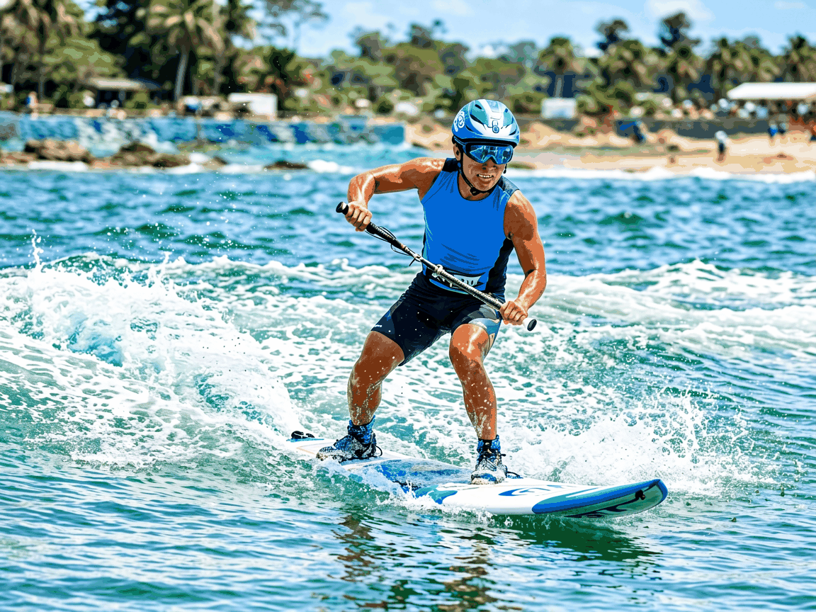
Custom efoil systems are deployed in recreational, instructional, and patrol applications where silent, zero-emission water access is valued. In training environments, lower-power configurations with stable, high-lift foils allow beginners to focus on balance and throttle control without excessive speed. Adjustable mast height enables progressive skill development as riders gain confidence.
For wave riding or downwinding, higher-aspect foils with reduced drag and increased glide efficiency are preferred. These configurations require precise tuning of fuselage length and mast rake to maintain pitch stability at speed. Custom winglets or wingtip fences may be added to mitigate tip vortices and improve lift distribution.
In saltwater environments, material selection and sealing integrity are paramount. Routine maintenance includes rinsing with fresh water after use, inspecting seals and gaskets for wear, and checking bolt torque on critical joints. Cathodic protection (e.g., zinc anodes) may be applied to exposed aluminum components to mitigate galvanic corrosion.
Regulatory compliance varies by jurisdiction—some regions classify efoils as vessels subject to speed limits, licensing, or equipment requirements (e.g., PFD, whistle). Suppliers should provide documentation on maximum speed, power output, and noise levels to assist buyers in meeting local regulations. CE marking or FCC/IC certification may be required for electronic components.
Inquiry and Specification Process
To initiate a custom efoil surfboard specification, buyers should provide: target rider weight range, intended use case, typical operating environment (salt/fresh water, wave conditions), desired ride time, and any regulatory constraints. Additional inputs such as preferred control interface type, battery placement constraints, or accessory requirements (e.g., camera mounts, GPS tracking) help refine the solution.
The supplier will respond with a preliminary feasibility assessment, including estimated weight, power requirements, and hydrofoil sizing. Iterative feedback loops refine the design using CFD simulations or tank testing data where applicable. Final approval includes detailed drawings, material certifications, and test protocols before production begins.
Lead times typically range from 6 to 12 weeks depending on complexity and material availability. Prototyping options are available for validation of hydrofoil performance or ergonomics. Shipping is arranged via crated packaging with foam bracing and moisture barriers to protect components during transit.