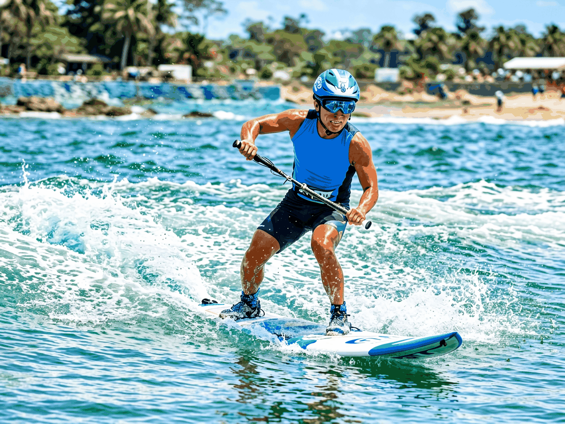
High Power Electric Surfboard
High Power Electric Surfboard
High power electric surfboards represent a specialized class of personal watercraft that integrate electric propulsion systems into hydrofoil or displacement hull designs to achieve elevated performance thresholds for recreational and professional use. Unlike conventional electric surfboards constrained by lower torque and energy density limits, these systems are engineered to deliver sustained thrust exceeding 15 kW, enabling planing speeds above 35 km/h and improved responsiveness in variable water conditions. This technical overview details the core subsystems, performance parameters, and engineering considerations that define high power electric surfboards for industrial buyers evaluating propulsion integration, battery systems, and control architecture.
Propulsion System Architecture
The propulsion system centers on a brushless DC motor with permanent magnet rotor, typically rated between 15–30 kW peak power and 80–150 Nm torque, mounted internally within a sealed nacelle to minimize drag and protect against water ingress. Motor efficiency is optimized through laminated steel cores and skewed slot design to reduce cogging torque and iron losses, achieving continuous efficiency above 90% in the 20–25 kW operating band. Heat dissipation relies on direct liquid cooling via glycol-water mixture circulated through stator jackets, maintaining winding temperatures below 120°C under sustained load.
Thrust is transmitted through a fixed-ratio gearbox (typically 3:1 to 5:1 reduction) driving a proprietary impeller or propeller enclosed in a duct to enhance propulsive efficiency and prevent cavitation at high RPM. The duct design incorporates flow strakes to manage vortices and improve inlet flow uniformity, contributing to a propulsive coefficient of 0.6–0.7 under planing conditions. Motor controller employs field-oriented control (FOC) with sensorless estimation or resolver feedback, enabling torque bandwidth up to 500 Hz and regenerative braking capability to recover energy during deceleration or wave trough passage.
Energy Storage and Power Delivery
Battery systems utilize lithium-ion cells with nickel-manganese-cobalt (NMC) or lithium-iron-phosphate (LFP) chemistries, configured in 400–800V nominal packs to minimize conduction losses in high-current wiring. Typical energy density ranges from 180–250 Wh/kg for NMC and 90–120 Wh/kg for LFP, with pack capacities between 3–6 kWh enabling 15–30 minutes of high-power operation depending on duty cycle. Cell balancing is managed via active shunt circuits, and thermal monitoring occurs at the cell group level to detect anomalies before propagation.
Power delivery employs segmented busbars with low-inductance layout to reduce voltage sag during peak current draw exceeding 400A. Pre-charge circuits limit inrush current during contactor closure, while main contactors rated for 800A DC interrupt fault currents within 2ms. System isolation monitoring continuously checks insulation resistance between high-voltage components and chassis, triggering shutdown if resistance drops below 500 kΩ to prevent shock hazards.
Hull and Hydrofoil Integration
Hull construction employs vacuum-infused carbon fiber-reinforced polymer (CFRP) with epoxy resin, achieving specific stiffness above 80 GPa·cm³/g and impact resistance through strategic ply orientation—0°/±45°/90° layups optimized for bending and torsional loads encountered during planing and wave impact. Surface finish targets Ra < 0.8 μm to minimize skin friction drag, validated via wind tunnel testing of scaled models. Buoyancy chambers are sealed using closed-cell foam cores with moisture barriers to prevent long-term water absorption and weight gain.
Hydrofoil variants incorporate fully submerged T-foils or V-foils with adjustable angle of attack via electric actuators, enabling dynamic lift control between 0° and 8° to maintain hull clearance of 15–25 cm above water surface at speeds exceeding 20 km/h. Foil sections use NACA 63-412 or custom profiles with thickness-to-chord ratios of 12–15% to delay cavitation onset. Structural joints between foil and fuselage use titanium pins and carbon-fiber sockets designed for 10⁵ load cycles at 1.5x maximum expected lift.
Control System and User Interface
The control system integrates a 32-bit microcontroller running real-time operating system (RTOS) with CAN bus communication between motor controller, battery management system (BMS), throttle input, and inertial measurement unit (IMU). Throttle input comes from a hall-effect trigger or pressure-sensitive grip, providing 0–100% command resolution with <10ms latency. IMU data (9-axis: accelerometer, gyroscope, magnetometer) feeds into sensor fusion algorithms to estimate pitch, roll, and yaw rates for stability augmentation and automatic trim adjustment.
User feedback is delivered via OLED display mounted on the handlebar, showing speed, battery state-of-charge, power consumption, and fault codes. Wireless connectivity (BLE 5.0) enables smartphone app pairing for firmware updates, ride logging, and geofencing. Safety systems include automatic motor cutoff upon detachment (via lanyard switch), overcurrent protection, and thermal throttling if inverter or battery temperatures exceed thresholds.
Performance Characteristics and Operational Limits
Typical performance metrics for a 20 kW system include: acceleration from 0 to 20 km/h in under 4 seconds, maximum speed of 38–45 km/h depending on hull design and water conditions, and range of 8–15 km at mixed throttle (50% average power). Climbing ability is limited by power-to-weight ratio; sustained ascent against 10% grade requires >250 W/kg, achievable only with lightweight hulls (<25 kg) and high-energy batteries. Saltwater operation increases corrosion risk, necessitating rinsing protocols and use of marine-grade stainless steel (AISI 316) for exposed fasteners and shafts.
Environmental operating limits are defined as: water temperature 0–40°C, wave height <0.5 m for stable planing, and salinity up to 35 ppt. UV exposure degrades surface coatings over time; topcoats with UV stabilizers (HALS) are recommended for tropical deployment. Storage state-of-charge should be maintained between 30–50% for long-term periods to minimize calendar aging of lithium-ion cells.
Typical Specifications Table
| Parameter | Typical Value | Notes |
|---|---|---|
| Peak Motor Power | 15–30 kW | Dependent on cooling and controller limits |
| Continuous Power | 10–20 kW | Thermal limited at ambient >25°C |
| Battery Voltage | 400–800V DC | Nominal pack voltage |
| Battery Capacity | 3–6 kWh | Usable energy, 80% DoD |
| Maximum Speed | 35–45 km/h | Planing hull, calm water |
| Acceleration (0–20 km/h) | <4 seconds | Throttle step input |
| Operating Temperature | 0–40°C (water) | Derate power above 30°C |
| Chassis Material | Carbon fiber/epoxy | Vacuum-infused, Tg >180°C |
| Weight (excluding battery) | 18–25 kg | Hull, motor, foils, controls |
| Ingress Protection | IP68 (submerged components) | Motor, controller, connectors |
Applications and Use Case Rationale
High power electric surfboards serve niche applications where internal combustion engines are impractical due to emissions, noise, or maintenance complexity. In coastal rescue operations, they enable rapid deployment of lifeguards through surf zones without wake disturbance, preserving victim visibility and reducing collision risk. Their silent operation supports marine wildlife monitoring, allowing researchers to approach species at close range without behavioral disruption caused by engine noise or exhaust.
In professional training environments, such as lifeguard academies or special forces maritime units, the consistent torque delivery and programmable power limits allow instructors to standardize drills across trainees, eliminating variability introduced by fuel levels or engine tuning. For rental operations in regulated zones (e.g., marine sanctuaries, no-wake areas), zero-emission compliance avoids permitting restrictions while meeting noise ordinances below 50 dB(A) at 15m distance.
Recreational users benefit from reduced operational complexity—no fuel mixing, winterization, or spark plug maintenance—lowering the barrier to entry for novice riders. The instant torque availability facilitates learning balance and wave timing, as power responds immediately to rider input without throttle lag. Fleet operators appreciate predictable service intervals; brushless motors require no commutator replacement, and sealed bearings eliminate lubrication points, reducing annual maintenance to inspection of seals, firmware updates, and visual checks of hydrofoil integrity.
Customization and Integration Options
Motor power rating can be scaled between 10–35 kW by adjusting stator stack length and magnet grade, allowing optimization for specific hull displacement or target speed. Battery chemistry selection (NMC vs LFP) trades energy density for thermal stability and cycle life; LFP is preferred for rental fleets requiring >2000 cycles, while NMC suits performance-oriented users prioritizing weight reduction. Nominal voltage is configurable in 50V increments to match available charging infrastructure or grid compatibility.
Hull length ranges from 160–200 cm, affecting stability and maneuverability; shorter lengths improve turning radius for surf applications, while longer hulls increase directional stability for open-water transit. Hydrofoil geometry—span, aspect ratio, and section—can be tuned for target speed envelope; high-aspect foils (>5) reduce induced drag at cruise but increase sensitivity to pitch disturbances. Control software permits adjustment of acceleration curves, regenerative braking strength, and speed limits via OTA updates to align with user skill level or regional regulations.
Optional modules include GPS-based geofencing for restricted zone enforcement, collision avoidance algorithms using forward-looking sonar, and modular battery packs enabling hot-swap operations for continuous fleet use. Mounting interfaces for accessories (camera, lights, sonar) follow MIL-STD-810G standards for vibration and shock resistance, ensuring reliability in dynamic environments.
Quality Control and Manufacturing Considerations
Production begins with automated fiber placement for hull preforms, ensuring consistent ply orientation and resin distribution. Vacuum infusion pressure is monitored in real time to maintain target fiber volume fraction (55–60%), verified via ultrasonic thickness mapping post-cure. Motor stator winding uses hairpin technology with automated insertion and laser welding to minimize resistance variation between phases (<5%). Final assembly includes torque-controlled fastening of critical joints (foil attachments, motor mounts) using calibrated digital wrenches with data logging.
Each unit undergoes hydrostatic pressure testing of sealed compartments to 0.5 bar gauge for 10 minutes to validate seal integrity. Motor insulation resistance is measured at 500V DC, requiring >100 MΩ between windings and ground. Dynamic testing includes no-load run-up to maximum RPM to detect imbalance, followed by loaded thrust measurement via dynamometer to verify power output within ±5% of target. Battery packs undergo capacity grading and impedance matching before installation to ensure balanced current sharing.
Final validation includes a 30-minute operational cycle simulating real-world usage: acceleration bursts, steady cruise, and regenerative braking, with temperature logging of motor, inverter, and battery. Units failing to maintain >85% efficiency or exhibiting >10°C rise in critical components are rejected. Packaging uses molded EPP foam inserts with humidity indicators to detect moisture ingress during transit, and external crating meets ISPM-15 standards for international shipment.